CONTACT & STAFF
For more information on this beamline, contact us.


The imaging beamline, IMX, at LNLS extracts synchrotron radiation from bending magnet D6 with magnetic field of 1.67 T and bending radius of 2.736 m. It has an electron source size of 391 µm x 97 µm and beam divergence of 808 µrad x 26 µrad and was designed to operate in either white beam or monochromatic beam. Monochromatic elements are Si(111) and a Ru/B4C Multilayer pair, located 12 m downstream from the source, and range in energy spectrums from 5 keV to 14 keV. Monochromatic elements can be removed from the beam to allow white light to enter the hutch. Pink beam energy spectrum ranges from 5 keV to 20 keV.
On entering the beamline, the beam is conditioned by white beam slits, before passing through a water-cooled Beryllium window (125 µm thick) positioned in front of the monochromator. Following this, the beam passes through the final Beryllium window which separates the vacuum from the air in the experimental hutch then, a small nitrogen filled ion chamber. The fast shutter controls the dosage on the sample, before the beam passes through a small vacuum section, provided by two Kapton windows (25 µm thick). A set of carefully optimised filters are available, which can be inserted into the beam path to remove low energies. These are particularly useful when imaging heavier or fragile samples where the lower energies either significantly damage the sample or result in beam hardening. The set consists of 4 highly polished Si filters of 200 and 350 µm thickness that can be combined to offset the average energy. Finally, a set of high precision slits defines the beam profile just before the sample.
The sample stage is located a few centimeters downstream of this set of slits. This stage allows for 2-dimensional translation (in the plane perpendicular to x-ray beam propagation) with sub-0.1 micron precision, to allow positioning of the sample within the x-ray beam, or to allow tiling of images. An air-bearing rotation stage, used for tomography scans, sits on the translation stage. Two high precision linear stages, mounted transversely to each other, allowing positioning of the sample over the axis of rotation. A magnetic sample mount is placed on top of the rotation stage, to locate the sample on the stage.
After passing through the sample, the X-rays pass through a thin vitrous carbon glass cover to enter a light-tight camera box. The x-rays reach a scintillator, which produces visible light; the local contact will select from one of 6 available scintillators; scintillator materials include Tb:LSO, LuAG, GGG, and Yag:Ce, of varying thicknesses, each optimized for work at different resolutions. Directly behind the scintillator is a mirror, set at a 45 degree angle. A turret containing long working distance lenses can then be used to image the scintillator onto a pco.2000 CCD camera. The objective is mounted on a stage which controls the image focus. The image recorded by the camera corresponds to a parallel projection of the sample onto the scintillator by the x-ray beam. In tomographic scans, a series of projection images are taken while the sample is usually rotated 180 degrees. The entire camera box move on two stages, which allows the sample-to-detector distance to be varied from a minimum of approximately 1 mm to a maximum of 300 mm and height to be adjusted given the monochromatic beam offset.
The IMX Beamline also has an automatic sample exchange system, which allow the creation of experiment queues, improving the efficiency and automatization of the beamline. This system uses a Mitsubishi RV-2F-D1 robot (CR750-D1 controller) to do the sample exchanging. Sensors were implemented on sample table to give a feedback to the system about the sample existence or not on the position, avoiding problems on queue creation and robot movement.
For more information on this beamline, contact us.
The following experimental techniques and setups are available to users in this beamline. To learn more about the techniques’ limitations and requirements (sample, environment, etc.) contact the beamline coordinator before submitting your proposal.
Tomography is a non-invasive imaging technique that allows to examine slices of a sample without damaging it. While radiography provides an image from a single orientation of the sample, tomography provides many images of the sample from different orientations, resulting in a set of projections or sinograms. Essentially, each sinogram column corresponds to the X-ray projection at one angle. This data can then be reconstructed by basically solving the inverse Radon transformation.
In our case, filtered back projection is used to reconstruct 3D images from a series of 2D projections. The projection values are smeared back across the 2D projections and integrated across all angles. To reduce blurring effects, the images are filtered in Fourier space before being back projected.
Similar to tomography, this method involves placing the detector some distance from the sample, so that the radiation refracted from the sample can interfere with the unchanged beam. Given the high degree of coherence available in synchrotron radiation, interference patterns or Fresnel fringes can be observed some distance away from the sample. Using this technique allows us to enhance the contrast observed in absorption images or separate entirely the phase (phase retrieval) and attenuation components. This method is particularly useful when investigating light materials or biological samples or even composites made from similar materials.
This technique is based on the Talbot effect, which is a Fresnel diffraction effect and leads to repetition of a periodic wavefront after a certain propagation distance, called the Talbot length. By placing a phase grating behind the sample, the interference pattern of the Talbot effect is modified by absorption, refraction and scattering in the sample. This interference pattern can then be analysed using a second absorption grating, which transforms the local fringe position into signal intensity variation on the detector. Along with the conventional transmission image of a sample, it provides both a differential phase contrast and a dark field image of the sample, by stepping the phase grating over a single period. Applications range from medical imaging of soft tissues, to food screening and measuring short range order in mesoscale systems.
| Element | Type | Position [m] | Description |
|---|---|---|---|
| Source | Bending Magnet | – | Bending Magnet D06 exit B (15°), 1.67 T , 391 µm x 97 µm |
| Window | Beryllium Window | – | PF1 125 µm thick |
| Mono | Double Multilayer Monochromator | 12 | Water-cooled Ru/B4C |
| Mono | Double Crystal Monochromator | 12 | Water-cooled Si(111) |
| Window | Beryllium Window | – | PF1 125 µm thick |
| Filters | Xia Filter | 22 | Si(111) 200 µm, 350 µm |
| Parameter | Value | Condition |
|---|---|---|
| Energy range [keV] | 5 – 20 | Pink Beam |
| Energy range [keV] | 5 – 14 | Si(111) DCM / Multilayer DMM |
| Energy resolution [ΔE/E] | 1.3 x 10⁻⁴ | Si(111) |
| Energy resolution [ΔE/E] | 1.4 x 10⁻² | Ru/B4C ML |
| Beam size at sample [mm2, FWHM] | 13 x 10 | Pink Beam |
| Beam size at sample [mm2, FWHM] | 13 x 4 | Si(111)/ML at 8keV |
| Beam divergence at sample [mrad2, FWHM] | 1 x 0.1 | at 8 keV |
| Flux density at sample [ph/s/mm2] | 8.61 x 10¹³ | Pink Beam |
| Flux density at sample [ph/s/mm2] | 1.84 x 10⁸ | Si(111) at 8 keV |
| Flux density at sample [ph/s/mm2] | 1.22 x 10¹⁰ | ML at 8 keV |
| Instrument | Type | Model | Manufacturer | Specifications |
|---|---|---|---|---|
| Detector | Area | pco.2000 | 7.4 µm pixel, 2048 x 2048 pixel, 14-bit CCD cooled camera | PCO |
| Microscope | Optical | Low-Dose | Monochromatic microscope, 3 objectives in-line: x2, x4, x10 | Optique Peter |
| Microscope | Optical | High-Dose | White beam microscope, single objective: x5 or x10 | Optique Peter |
| Scintillator | High Flux | LuAg:Ce | φ10mm, 50µm, φ15mm, 5µm | Crytur |
The LNLS X-Ray Imaging Beamline (IMX) uses a National Instruments PXI-6602 timing board attached to an NI PXI-1045 chassis to read digital counters and trigger devices during scans. A PiMicos UPR-160 rotation stage performs the sample rotation during tomography. The scan points are programmed directly on a Hydra SMC motion controller as a function of parameters passed from EPICS PV’s to reduce latency between scan points and enable quick tomography. The controller sends feedback through the I/O interface on trip-point arrival and transmits the present motion status, enabling hardware synchronization between motors and scan devices. A LabVIEW VI running on a dedicated Windows Machine controls a pco.2000 camera, which is currently the main detector at IMX Beamline. The user interface screens run from a workstation on CS-Studio environment under Linux Red Hat operational system. CS-Studio inputs integrate to EPICS via Py4Syn scripts to run scan routines and set up experiments.
Data visualization and analysis
IMX uses Avizo to visualize and analyze scientific and industrial 3D data acquired with X-ray imaging (IMX). Avizo is a powerful software application offering abundant state-of-the-art image data processing, exploration, and analysis features for understanding 3D images by extracting properties, statistics, models, and more from the original grayscale data. Learn more at www.Avizo3D.com.
Click here to Download the Beamline Manual.
IMX uses Avizo to visualize and analyze scientific and industrial 3D data acquired with X-ray imaging (IMX). Avizo is a powerful software application offering abundant state-of-the-art image data processing, exploration, and analysis features for understanding 3D images by extracting properties, statistics, models, and more from the original grayscale data. Click here to Download the Manual.
Another program that IMX uses is Fiji, an ImageJ distribution that includes many useful plugins developed by the community. Specifically, Trainable Weka Segmentation, which uses machine learning to automate the segmentation of images, is used. Click here to Download the Manual.
Annotat3D, a software developed by CNPEM’s Scientific Computing Group, is also used. It uses machine learning with a superpixels/supervoxels technique for more efficient segmentation. It also utilizes Deep Learning for supervised learning to segment a series of similar images. Click here to Download the Manual.
Users are required to acknowledge the use of LNLS facilities in any paper, conference presentation, thesis and any other published material that uses data obtained in the execution of their proposal.
Scientific publications produced with data obtained at the facilities of this beamline, and published in journals indexed by the Web of Science, are listed below.
Ferreira, T. R.;Archilha, N.L.;Pires, L. F.. An analysis of three XCT-based methods to determine the intrinsic permeability of soil aggregates, Journal of Hydrology, v.612, p.128024, part A, 2022. DOI:10.1016/j.jhydrol.2022.128024
Avelino, T. M. ;García-Arévalo, M. ;Torres, F. R. ;Dias, M. N. G. ;Domingues, R. R.;Carvalho, M. de;Fonseca, M. de C.;Rodrigues, V. K. T. ;Paes Leme, A. F.;Figueira. A. C. M.. Mass spectrometry-based proteomics of 3D cell culture: A useful tool to validate culture of spheroids and organoids, SLAS Discovery, v.27, n.3, p.167-174, 2022. DOI:10.1016/j.slasd.2021.10.013
Novais, S. M. V.;Monteiro, T. de J.;Andrade, A. B.;Gomes, M. A.;Dias, C. S. B.;Valerio, M. E. G.;Macedo, Z. S.. Development of CdWO4-polystyrene scintillator composites for X-ray detection in imaging systems, Nuclear Instruments & Methods in Physics Research Section A-Accelerators Spectrometers Detectors and Associated Equipment, v.1025, p.166196, 2022. DOI:10.1016/j.nima.2021.166196
Silva, W. B. ;Leiva, D. R.;Floriano, R.;Vega, L. E. R. ;Oliveira, V. B.;Gallego, J. ;Figueroa, S. J. A.;Miqueles, E. X.;Silva, E. P. da ;Ishikawa, T. T.;Botta Filho, W. J.. Magnesium Alloys for Hydrogen Storage Processed by ECAP Followed by Low Temperature Rolling, Materials Research-Ibero-american Journal of Materials, v.25, p.e20210214, 2022. DOI:10.1590/1980-5373-MR-2021-0214
Rosso, D. F. ;Driemeier, C. E.;Negrão, D. R.. Unveiling the Variability and Multiscale Structure of Soybean Hulls for Biotechnological Valorization, Waste and Biomass Valorization, v.13, n.4, p.2095-2108, 2022. DOI:10.1007/s12649-021-01655-z
Paiva, K. ;Meneses, A. A. de M. ;Barcellos, R. ;Moura, M. S. dos S.;Mendes, G.;Silva, G. F. Q. da;Sena, G.;Colaço, G.;Silva, H. R. da ;Colaço, M. V. C.;Barroso, R. C.. Performance evaluation of segmentation methods for assessing the lens of the frog Thoropa miliaris from synchrotron-based phase-contrast micro-CT images, Physica Medica-European Journal of Medical Physics, v.94, p.43-52, 2022. DOI:10.1016/j.ejmp.2021.12.013
Longhi, M. A. ;Rodríguez, E. D.;Walkley, B.;Eckhard, D. ;Zhang, Z. ;Provis, J. L. ;Kirchheim, A. P.. Metakaolin-based geopolymers: Efflorescence and its effect on microstructure and mechanical properties, Ceramics International, v.48, n.2, p.2212-2229, 2022. DOI:10.1016/j.ceramint.2021.09.313
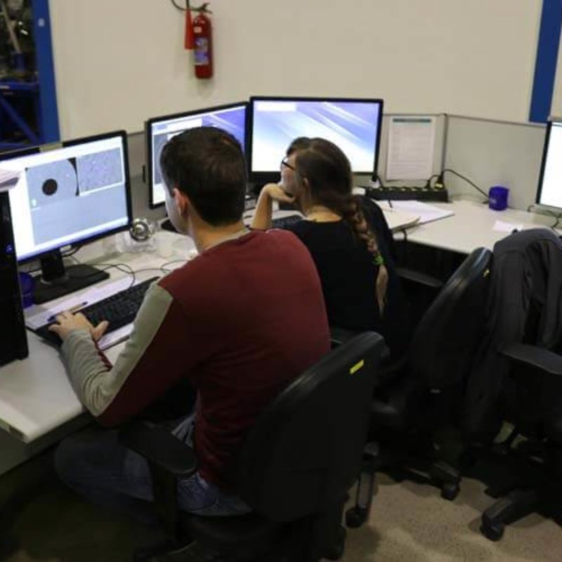
Português:
Usuários fazendo a segmentação das imagens obtidas.
English:
Users doing images segmentation.
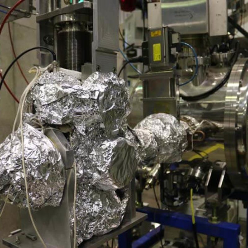
Português:
Monocromador da linha IMX.
English:
Monochromator of IMX Beamline.
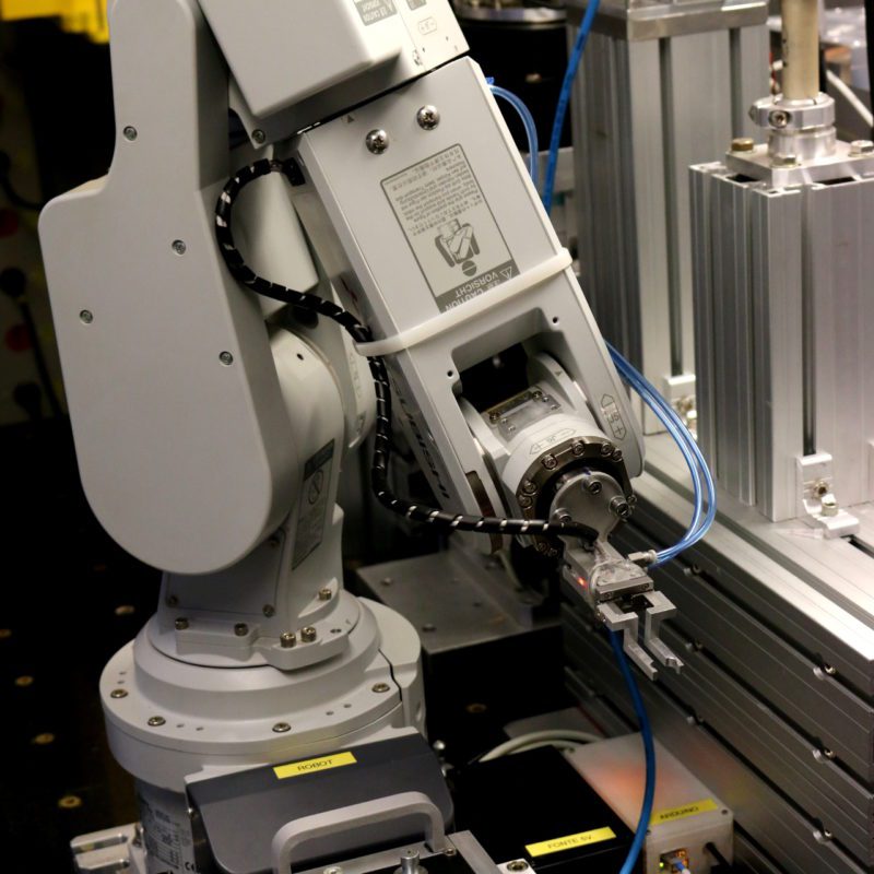
Português:
Sistema automático para troca de amostras.
English:
Automatic sample exchange system.
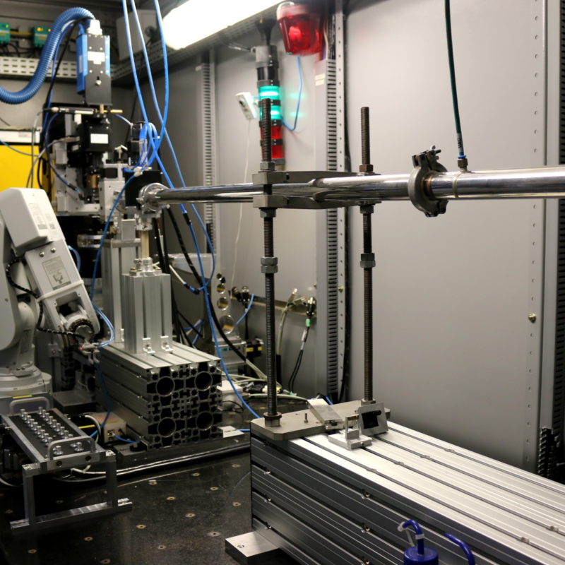
Português:
Cabana experimental.
English:
Experimental hutch.
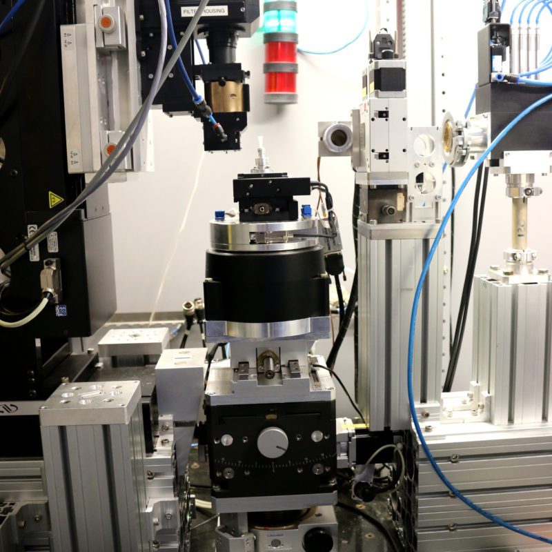
Português:
Estágios para posicionamento da amostra com seis graus de liberdade
English:
Sample stage with six degrees of freedom.
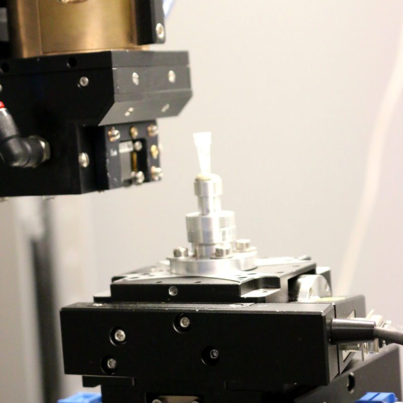
Português:
Amostra e janela do detector
English:
Sample and detector window.
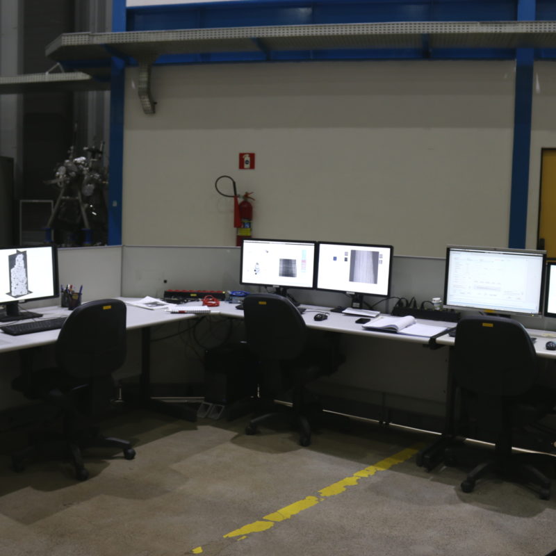
Português:
Estação de controle da linha.
English:
Beam line control station.
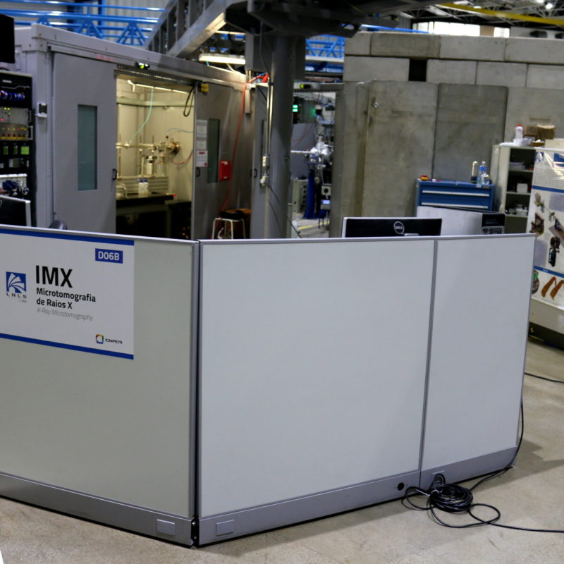
Português:
Vista panorâmica da linha IMX.
English:
Panoramic view of IMX Beamline.